Maintenance and Inspection
Condition Based Maintenance and safety checks by Hosokawa Alpine Blueserv.
Unplanned downtime costs time and money. With proactive maintenance and regular inspection, we keep your equipment reliably available and protect both people and machinery. To achieve this, we continuously monitor the condition of your machine drives through Condition Based Maintenance and assess the safety of your entire system in regular checks.
Condition-based maintenance of machine drives
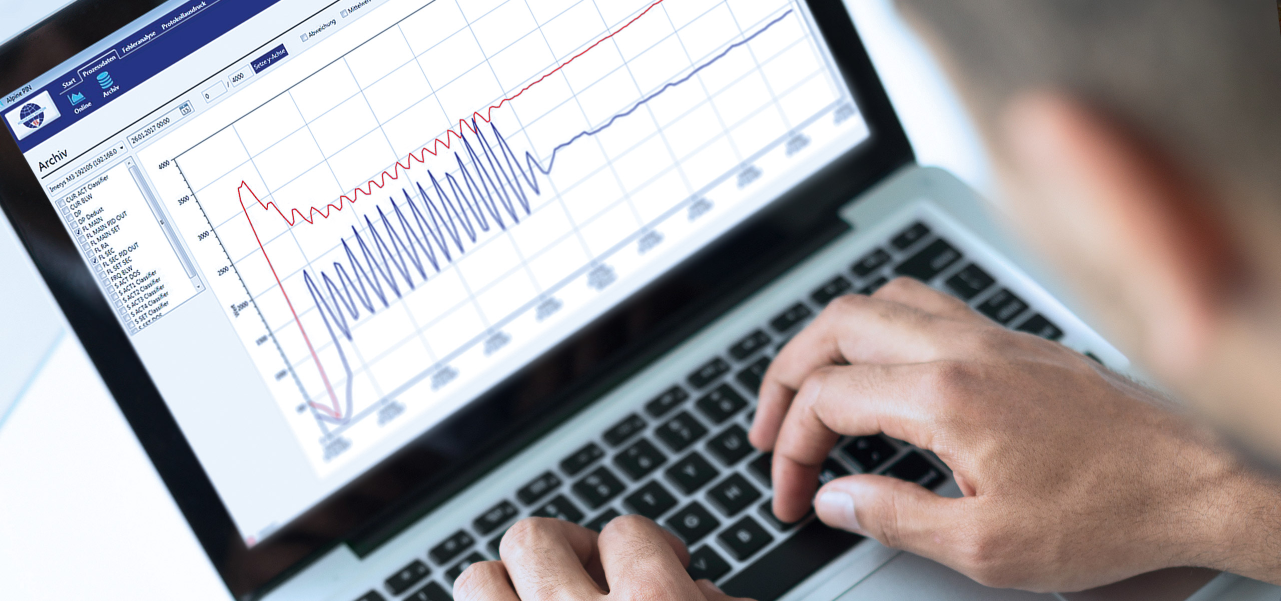
Condition Based Maintenance (CBM)
CBM was developed for monitoring the status of machine components (ball bearings, rinsing airs and temperatures.), thus allowing the customer to draw up an optimum plan of the requisite maintenance measures, but is also in a position to prevent consequential damage to the machine.
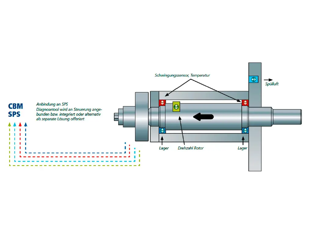
Bearing Diagnosis
Diagnosis of the bearing is also performed by the vibration sensor. At present, the envelope curve and acceleration value of the inner race, outer race and rolling elements, as well as the envelope curve and acceleration of the entire bearing are monitored for this diagnosis, all in all eight measured values. The parameters for the ball bearing type and system component will be exactly assigned in the sensor.
The sensor transmits the collective alarm (switching contact) of the parameterised values to the PLC. The visualisation system generates the respective messages and displays them. The alarm factor is selected such that enough time remains to react without having to fear a sudden standstill of the system caused by bearing failure.
Bearing temperature
The temperatures of the fixed and floating bearings are detected by two PT100 temperature sensors. The analogue temperature signal (3-wire RTD sensor) is transmitted to the PLC unit. The limit values are configured in the PLC unit and signalise the condition in the form of a set of traffic lights on the visualisation system.
Total machine vibrations
The total vibration value, also known as the effective vibration value, is detected by a vibration sensor and transmitted to the PLC unit in the form of an analogue signal (0-10 V or 4-20 mA). The effective value includes all vibrations occurring in the machine in the range from 10 to 1000 Hz. It can be used as a diagnostic tool for the unbalance of the machine. The limit values are configured in the PLC unit and signalise the condition in the form of a set of traffic lights on the visualisation system.
Rising air flow rate
The flow rates of the classifying wheel gap rinsing air and the bearing rinsing air are detected by means of suitable flowmeters. The analogue air flow rate signal (4-20 mA) is transmitted to the PLC unit.
The limit values are configured in the PLC unit and signalise the condition in the form of a set of traffic lights on the visualisation system.
Safety Check
for maximum safety
Alongside the operational safety of a system, the safety of employees is the top priority. This can be ensured through tailored consulting and inspection services.
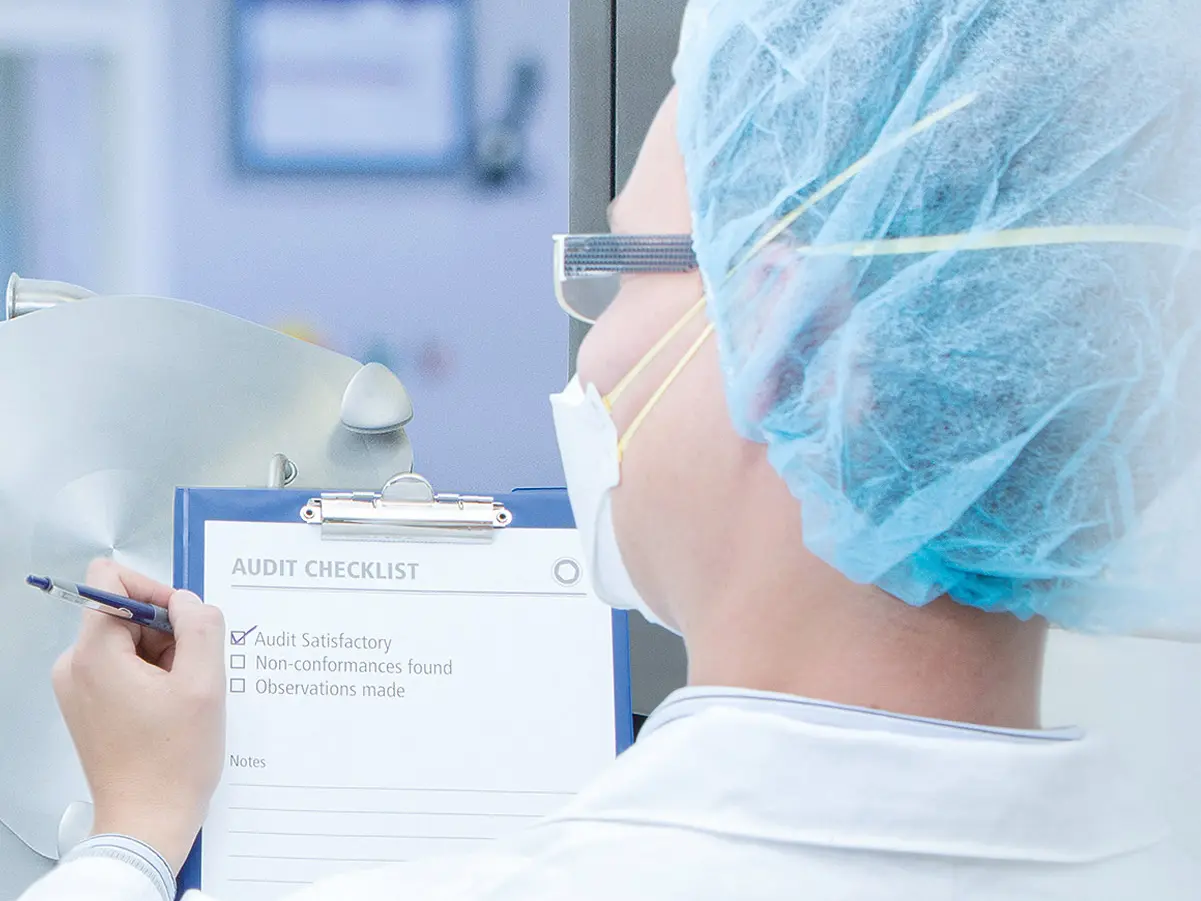
Mechanical Safety-Check
With a mechanical safety check, your machine will be tested according to the latest European safety standards. Machines handling explosive dust products will be checked for conformity with the latest ATEX standards and modifications will be suggested if necessary. We also handle any CE-certification requirements.
Electro-Check
In order to comply with the accident-prevention regulations for electrical installations and equipment (DGUV Rule 3), your Hosokawa Alpine machine must be checked every four years. We take care of the complete test, including measuring grinding quality, insulation and differential current.
Our effective accident-prevention program
- Preventing injury, product loss or equipment damage due to missing safety locks
- Preventing injury and fire damage following explosion impact on non-shock resistant components
- Minimize risk of serious injury to workers from rotating parts by installing effective protective guards